


Copyright © 2014 mat - Maschinen- und Anlagentechnik Dr. Becker GmbH - Last Update: 30.07.2019
Phase Grounding
Ground fault in medium voltage networks
Relief of fault location by Phase Grounding and Earth Fault Detection
The phase grounding is useful applicated in inductive grounded medium voltage networks by arc
suppression coils. The use in isolated systems is also possible. During a single-pole ground fault due to the
earth capacitance of the cables or overhead lines a capacitive charging current is flowing through the fault
place.
Through the use of arc suppression coils, which is connected in the neutral point of the power transformer
or is switched to the neutral point of a grounding transformer, inductive compensation current (180 ° phase)
flows in the event of a ground fault on the fault place.
Through accurate compensation by means of an adjustable plunger core arc suppression coil and a
qualified compensation controller, the capacitive charging current can be brought to zero (in case of
resonance tuning). At the fault location only the “Watt residual current” remains, which however in large
cable networks can have quite a couple of
amps. In case of over- or under-
compensation (detuning), an additional
reactive current flows over the fault location
according to the detuning degree.
Generally, in Electrical Authority Networks
the resistive residual current amounts for
about 2-4% of the resonant current
(capacitive charging current or inductive
compensation current at resonance tuning)
but 6 – 8 % in Industrial Networks.
With the appropriate amount of the resulting residual current (apparent current) at the fault location
significant thermal damage can cause (I ² R). Therefore it is purposeful in selected applications to minimize
this current. In addition to ground fault of the 50 Hz component a 250 Hz component flows. As experiences
shows, the 250 Hz component can reach approximately 70-150% of the 50 Hz component. So it is obvious
that the fault place is stressed by the 50 Hz current and additionally by harmonic currents.
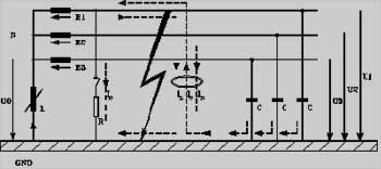
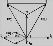
Demonstration of currents and voltages
during a ground fault.
Basically, there are two possibilities residual currents at the fault location to
compensate:
a)
The Residual Current Compensator by electronic converter
b)
The low resistant shunt by grounding the faulty phase at the
substation (Phase Grounding)
The Residual Current Compensator has sometimes considerable
disadvantages:
1.
Because of the complexity of the electronic converter up to now only the 50 Hz component will be
deleted. The almost equal 250 Hz component is not compensated.
2.
In the already complex zero sequence system during ground fault a converter can produce
unavoidable network perturbations.
3.
The compensation current is driven through may well branched lines through the fault site and thus
possibly in sensitive areas such as pits, underground mining operation or sensitive chemical plants.
4.
The cost of control electronics and power electronics are high, and the operational safety even
depends much on power disturbances (transient voltages).
5.
Reliability, durability and cost of maintenance are taken into account.
The phase grounding on the other hand provides a long-known and simple, robust and reliable
technology.
There the faulty phase is grounded at the substation. Disadvantages were previously that 3 -pole switching
devices and thus 3 switching cubicles had to be used. This also resulted in significant hardware cost and
because of the three switching cubicles to a significant space requirement (also an extra charge).
In addition in the solid phase grounding depending on the load current at the fault location, a certain voltage
drop occurs.
Due to new technological possibilities, we have made the phase grounding for practical use highly
interesting. By using 3 or 4 single-pole circuit breakers, which very small magnetic drives include, the cost
can be reduced to one switching cubicle.
Additionally required is a selection circuit to identify the faulty phase with interlocking and a defined switch-
on command. The disturbing voltage drop across the fault location is widely compensated by the use of a
power resistor.
Thus today we present a low-cost system, which the fault location relieves of residual current largely, both
of the active and the reactive component, and indeed in the entire frequency spectrum so fundamental and
harmonic currents.
Based on our many years of experiences in the area of ground fault treatment and the design of power
resistors, we were able to develop a wide variety of configurations. Typical is a type tested interior
switchgear cubicle with a built-on or separately standing control cabinet. Herewith is an affordable, flexible
and highly efficient system for relief of the fault
location available, which in particular, the interests of
sensitive and safety-related networks considered.
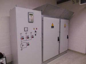
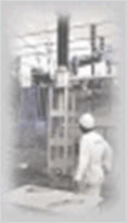
Control cabinet and switchgear panels
10.5 kV (25kA)
The newly development by our technique is forward-
looking, as costs, technology and effort are an optimal
relation to each other.
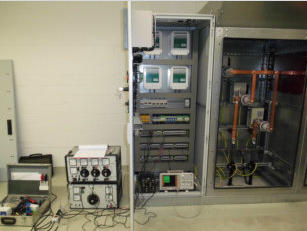
Calibration of the system
With the same facility and without additional effort, by inserting a defined short-time double- earth-
fault (KUDE) an effective earth fault detection can be obtained (duty cycle 100 msec.). Both for
isolated and compensated networks we possess corresponding patents.
For more information, please contact us.
Service:
Phone:
+49 4532 2021-01
Fax:
+49 4532 2021-21
Mail:
info@m-a-t.de